More and more project managers, architects, and engineers ask us to provide survey drawings tied to a specific datum, coordinate system, or rotation. Often, people refer to a
so-called “world coordinate system”, but in truth, no single system exists. There are many ways to create and present surveys—and none of them are perfect.
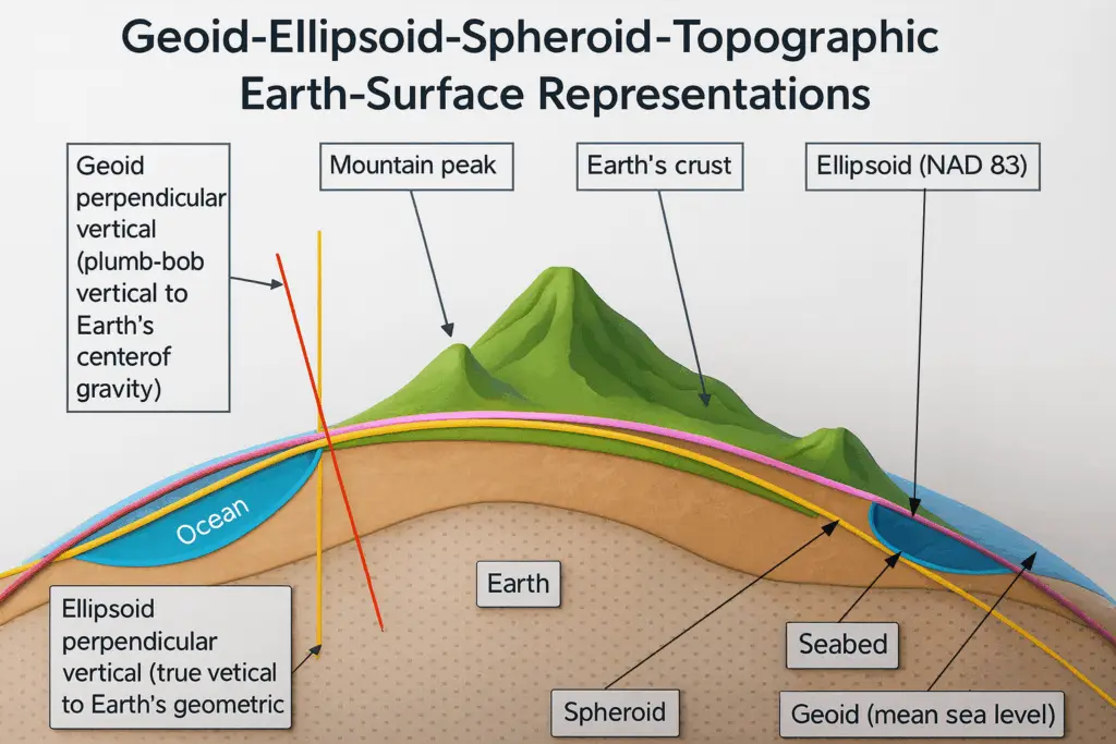
Here’s Why: Survey drawings use x, y, and z coordinates on a flat plane, while the earth itself is curved. Any coordinate system is just an approximation, a projection of the earth’s surface. Elevations (the z-coordinate) are based on a “zero” point—an approximation of sea level defined by a geoid model that best fits the earth’s irregular shape.
So, what really matters in practice?
1. A Reliable Benchmark
Every project needs a solid reference for elevations. This benchmark is a physical point from which all vertical measurements are taken. It might be:
- An existing published benchmark (such as a brass disc set by an agency).
- A new benchmark established with GPS (e.g., NAVD 88, accurate to about 0.1–0.2 feet).
- A stated assumed elevation (e.g., “100.00 feet”) for internal project consistency.
Sometimes we tie into benchmarks from previous or adjacent projects to ensure shared data.
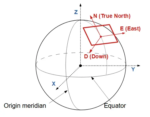
2. A Clear Basis of Bearing or Rotation
Drawings also need a rotation reference, so everyone understands how the project aligns with north. Options include:
- GPS measurements tied to global coordinate systems (e.g., NAD 83 California Zone 3).
- Record bearings from monument lines on recorded survey maps.
- Assumed rotations, such as “plan north” based on a building, property line, or prior project.
These approaches will not match exactly—but consistency and clarity are what matter.
The Takeaway
Survey control systems can be complex. That’s why early discussion and agreement on benchmarks, datums, and rotations are critical to a smooth project. Partnering with an experienced firm like Underwood & Rosenblum ensures these details are handled correctly—setting your project on the right path from the start.